Pre-Lab (PDF)
In Lab 4, we will use the same system that we studied in Lab 3. The objective of this lab is to observe the driven step response of a second order system and to tune the system's parameters to obtain a desired behavior. This can be done by adjusting the length of the spring rod and thereby changing the stiffness of the system. The voice coil that was short circuited in Lab 3 is used to supply the input force. A function generator and power amplifier provide a step in voltage to the voice coil, which results in a step in force on the shaft. The damping is fixed at the short-circuit value of Lab 3.

Figure 1. Idealization: spring, mass, damper with step force input. (Image by Prof. Trumper.)
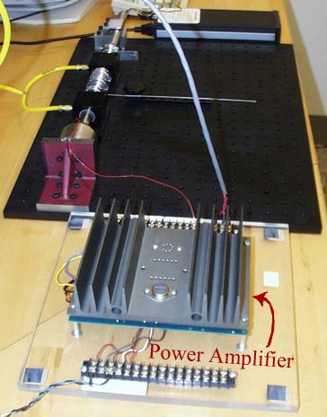
Figure 2: The power amplifier is an Apex PA21 power op-amp in their EK21 evaluation kit.

Figure 2. The power amplifier is an Apex PA21 power op-amp in their EK21 evaluation kit. (Image by Prof. Trumper.)
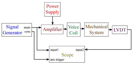
Figure 3 shows a circuit diagram of this lab.

Figure 3. Circuit diagram of this lab. (Image by Prof. Trumper.)
Materials and Notes: Practical Info and Comments
- As in Lab 3:
- Adjustable spring clamp
- Air bearings
- Angle plate
- Optical breadboard
- LVDT (Linear Variable Differential Transducer)
- Shaft and collars
- Spring
- Stand
- Voice coil
New
